

- English
 Español
 Português
 русский
 Français
 日本語
 Deutsch
 tiếng Việt
 Italiano
 Nederlands
 ภาษาไทย
 Polski
 한국어
 Svenska
 magyar
 Malay
 বাংলা ভাষার
 Dansk
 Suomi
 हिन्दी
 Pilipino
 Türkçe
 Gaeilge
 العربية
 Indonesia
 Norsk
 تمل
 český
 ελληνικά
 український
 Javanese
 فارسی
 தமிழ்
 తెలుగు
 नेपाली
 Burmese
 български
 ລາວ
 Latine
 Қазақша
 Euskal
 Azərbaycan
 Slovenský jazyk
 Македонски
 Lietuvos
 Eesti Keel
 Română
 Slovenski

Which Single-Sided Thermoelectric Separation Copper Substrate Delivers Reliable Thermal Performance?
High-power electronic components generate considerable heat during operation. Without an effective thermal management structure, excessive temperatures can reduce LED brightness, accelerate component aging, affect circuit stability, and shorten product service life. A single-sided thermoelectric separation copper substrate provides a specialized solution by separating the electrical circuit area from the primary heat conduction area.
Using copper as the thermal base, this substrate structure creates a direct heat transfer path for selected electronic components while maintaining electrical insulation between the circuit layer and the metal base. It is particularly relevant to high-power LED lighting, automotive lighting, industrial electronic equipment, and other applications with demanding heat dissipation requirements.
This guide explains its construction, operating principles, advantages, material considerations, manufacturing processes, and purchasing criteria. It also explores how manufacturers can evaluate a substrate design to achieve better thermal performance and reliable electrical insulation.
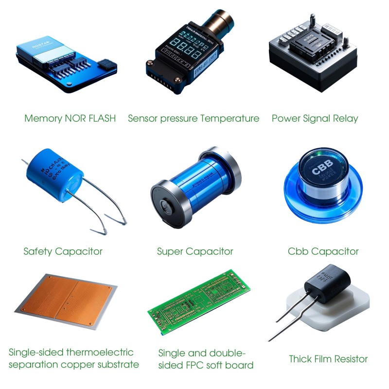
Table of Contents
- What Is a Single-Sided Thermoelectric Separation Copper Substrate?
- How Does the Thermoelectric Separation Structure Work?
- Key Structural Components and Functions
- Why Choose a Copper Substrate?
- Main Advantages for Electronic Applications
- Typical Applications Across Industries
- Important Technical Parameters to Consider
- Manufacturing Process and Quality Control
- Common Problems and Practical Solutions
- How to Select the Right Copper Substrate
- Frequently Asked Questions
1. What Is a Single-Sided Thermoelectric Separation Copper Substrate?
A single-sided thermoelectric separation copper substrate is a specialized metal-based circuit substrate designed to improve heat dissipation in electronic products. It generally consists of a copper base, an insulating layer, and a patterned copper circuit layer. Its distinguishing feature is the separation of the electrical connection area from the main thermal conduction area.
In a conventional metal-core PCB, the copper circuit layer is typically separated from the metal base by a continuous insulating dielectric layer. Although this structure provides electrical insulation and heat conduction, the dielectric layer can contribute additional thermal resistance between a heat-generating component and the metal base.
A thermoelectric separation structure addresses this limitation through a specially designed thermal contact region. The heat-generating component can be positioned over a designated copper thermal area that is directly connected to the copper base, while the surrounding electrical circuit remains insulated from the metal substrate.
This arrangement creates a more direct thermal pathway for the selected component without removing the electrical insulation required by the circuit.
Key principle: Thermoelectric separation refers to the structural separation of electrical conduction and heat dissipation areas. It does not mean that the substrate generates electricity through the Seebeck effect or provides active cooling through the Peltier effect.
What Makes It Different from a Conventional Copper PCB?
The main difference is the thermal connection between the component mounting region and the copper base. In a conventional insulated metal substrate, heat generally passes through the dielectric layer before reaching the metal base. In a thermoelectric separation design, the designated thermal region can bypass the conventional insulating layer to provide a more direct heat conduction route.
This structure is especially valuable when a component produces concentrated heat in a relatively small area, such as a high-power LED chip or automotive lighting module.
2. How Does the Thermoelectric Separation Structure Work?
The operating principle is based on separating two functional paths: the electrical connection path and the thermal conduction path. Each path is designed to perform a different task while working together within the same substrate.
2.1 The Electrical Conduction Path
The patterned copper circuit layer provides electrical connections between electronic components. It carries current through designed conductive traces and connection pads according to the circuit layout.
An insulating dielectric layer separates this circuit structure from the copper base. This prevents unwanted electrical contact between the circuit and the conductive metal substrate.
2.2 The Thermal Conduction Path
When an electronic component operates, it generates heat. In a thermoelectric separation design, the component's designated thermal contact area connects to a copper thermal region, which transfers heat toward the copper base.
The copper base then distributes the heat over a larger surface area and transfers it to an external cooling structure, such as a heat sink or metal housing, depending on the product design.
2.3 Why Thermal Separation Matters
In high-power applications, even a relatively thin insulating layer can influence the total thermal resistance. Reducing the number of thermal barriers in the main heat path can improve heat transfer efficiency.
However, the actual thermal performance depends on the complete assembly, including the component-to-substrate contact, copper geometry, base thickness, surface flatness, interface materials, and external cooling conditions.
Important engineering consideration: A direct copper thermal connection can reduce the contribution of the dielectric layer to thermal resistance, but it does not eliminate all thermal resistance. The complete thermal path must still be evaluated.
3. Key Structural Components and Functions
Understanding the substrate structure helps engineers and purchasing teams evaluate whether a product is suitable for their electronic application.
| Component | Main Function | Key Consideration |
|---|---|---|
| Copper Base | Provides the primary heat spreading and dissipation foundation. | Thickness, purity, flatness, and thermal conductivity. |
| Insulating Layer | Electrically isolates the circuit from the metal base. | Dielectric strength, thermal conductivity, and thickness. |
| Copper Foil | Forms the conductive circuit pattern. | Thickness, adhesion, and electrical performance. |
| Thermal Separation Region | Provides a designated heat transfer connection to the copper base. | Geometry, contact area, and dimensional accuracy. |
| Surface Finish | Supports solderability and protects exposed conductive surfaces. | Finish type, thickness, and application compatibility. |
Copper Base: The Foundation of Heat Dissipation
Copper is widely used in thermal management applications because of its high thermal conductivity. It helps spread localized heat from electronic components across a larger area, reducing concentrated hot spots when combined with an appropriate cooling system.
Insulating Layer: Electrical Safety and Reliability
The dielectric layer is essential because the copper base is electrically conductive. It must provide adequate electrical isolation while allowing heat to pass from the circuit region to the metal structure where required.
Its thermal conductivity, thickness, dielectric strength, bonding quality, and resistance to thermal aging all influence the overall substrate performance.
Copper Circuit Layer: Stable Electrical Connections
The copper foil is patterned to create the required circuit layout. Its thickness and geometry influence current-carrying capacity, resistance, soldering performance, and mechanical reliability.
4. Why Choose a Copper Substrate?
Material selection has a direct impact on thermal performance, mechanical stability, and manufacturing cost. Copper is often considered for applications where heat spreading is a major design priority.
High Thermal Conductivity
Copper efficiently transfers and distributes heat away from localized heat-generating components.
Effective Heat Spreading
The metal base helps distribute concentrated thermal loads across a larger area.
Mechanical Stability
A properly designed copper base provides structural support for demanding electronic assemblies.
Machining Flexibility
Copper can be processed into different shapes, thicknesses, and thermal structures according to design requirements.
Suitable for High-Power Designs
Its thermal properties make it useful for electronic products with concentrated heat generation.
Design Integration
Special thermal regions and mounting features can be incorporated into customized substrate structures.
Copper vs. Aluminum Substrates
Copper and aluminum are both used in metal-based electronic substrates. Copper generally offers higher thermal conductivity, while aluminum is lighter and may offer cost advantages for certain products.
| Comparison | Copper Substrate | Aluminum Substrate |
|---|---|---|
| Thermal Conductivity | Generally higher. | Generally lower. |
| Weight | Relatively heavy. | Relatively lightweight. |
| Heat Spreading | Excellent thermal spreading capability. | Suitable for many standard thermal applications. |
| Material Cost | Generally higher. | Generally lower. |
| Typical Applications | High-power LEDs and demanding thermal assemblies. | General LED lighting and electronic products. |
The right choice depends on the product's thermal requirements, weight limitations, production budget, and mechanical design. Copper should not automatically be selected for every application if aluminum can meet the required performance.
5. Main Advantages for Electronic Applications
5.1 Improved Heat Transfer Efficiency
The separated thermal region provides a direct heat transfer path between the designated component mounting area and the copper base. By reducing the thermal resistance associated with an intervening dielectric layer in this region, the design can support better temperature management.
This is particularly important for high-power LED assemblies, where junction temperature has a significant influence on light output, color stability, and component lifetime.
5.2 Better Temperature Management
Excessive temperature can accelerate semiconductor aging and affect solder joints, electronic connections, and surrounding materials. Effective heat spreading helps reduce localized temperature concentrations and supports more stable operating conditions.
5.3 Support for Compact Product Designs
Thermoelectric separation copper substrates can help designers integrate electrical and thermal functions into a compact structure. This is useful when equipment manufacturers need to balance limited installation space with increasing power density.
5.4 Improved Design Flexibility
The thermal contact area, circuit layout, copper base dimensions, and mounting structure can be designed around specific product requirements. Customized geometries may help simplify integration into LED modules, lighting housings, and electronic assemblies.
5.5 Potentially Longer Component Service Life
Keeping electronic components within their specified temperature range can reduce thermal stress and help prevent premature degradation. However, actual service life also depends on component quality, electrical loading, environmental conditions, and the complete cooling system.
6. Typical Applications Across Industries
Single-sided thermoelectric separation copper substrates are particularly relevant to electronic products where electrical insulation and efficient heat transfer must be achieved within a compact assembly.
6.1 High-Power LED Lighting
High-power LED chips generate heat in a concentrated area. If this heat cannot be transferred efficiently, the LED junction temperature may rise, potentially reducing luminous output and accelerating aging.
A thermoelectric separation copper substrate provides a dedicated thermal connection that helps transfer heat from the LED mounting region toward the copper base and external heat sink.
6.2 Automotive Lighting Systems
Automotive headlights, daytime running lights, and other LED lighting modules operate under demanding environmental and thermal conditions. Temperature fluctuations, vibration, and limited installation space create additional engineering challenges.
A properly engineered copper substrate can support thermal management in automotive lighting assemblies. Designers should also evaluate mechanical stress, dimensional stability, insulation reliability, and the product's complete environmental requirements.
6.3 Industrial LED Equipment
Industrial lighting systems may operate for extended periods in environments where consistent illumination is important. A suitable copper substrate can help manage heat generated by high-power LED components.
6.4 Power Electronic Assemblies
Some power electronic products contain components that produce concentrated heat during operation. Depending on circuit architecture and electrical isolation requirements, a customized thermoelectric separation substrate may be considered as part of the thermal management solution.
6.5 Specialized Electronic Devices
Other potential applications include high-power indicator lights, compact electronic lighting modules, and specialized equipment requiring an integrated electrical and thermal structure.
Application reminder: The suitability of a single-sided thermoelectric separation copper substrate depends on the actual component layout, voltage isolation requirements, heat generation, and mechanical installation conditions. Not every electronic product requires this specialized construction.
7. Important Technical Parameters to Consider
Choosing a copper substrate requires more than checking the copper thickness. Several parameters work together to determine thermal performance, electrical safety, and manufacturing consistency.
| Technical Parameter | What It Affects | What to Confirm |
|---|---|---|
| Copper Base Thickness | Heat spreading, mechanical strength, and weight. | Required dimensions and thermal load. |
| Copper Foil Thickness | Current-carrying capacity and circuit resistance. | Electrical load and circuit layout. |
| Dielectric Thickness | Electrical insulation and thermal resistance. | Required dielectric strength and thermal performance. |
| Thermal Conductivity | Heat transfer through the substrate materials. | Material specifications and test conditions. |
| Surface Flatness | Component mounting and thermal contact. | Assembly tolerances and mounting requirements. |
| Insulation Resistance | Electrical isolation reliability. | Applicable electrical testing requirements. |
| Bonding Strength | Layer adhesion and resistance to delamination. | Manufacturing quality and thermal cycling performance. |
| Dimensional Tolerance | Assembly accuracy and component positioning. | Product drawings and production tolerances. |
Understanding Thermal Resistance
Thermal resistance describes how strongly a material or interface opposes heat flow. For a simplified uniform material layer, it can be estimated using:
Rth = t / (k × A)
Where:
- Rth: Thermal resistance (K/W)
- t: Material thickness (m)
- k: Thermal conductivity (W/m·K)
- A: Effective heat transfer area (m²)
A thinner material layer, higher thermal conductivity, or larger effective heat transfer area can reduce the thermal resistance of that layer under the simplified assumptions.
In real assemblies, engineers must also account for contact resistance, interface materials, heat spreading, and the external cooling system. Therefore, the complete thermal path should be assessed rather than evaluating the copper substrate in isolation.
8. Manufacturing Process and Quality Control
Manufacturing a thermoelectric separation copper substrate requires accurate control of the copper base, insulating material, circuit pattern, and thermal separation geometry. Process selection depends on the specific design and production requirements.
8.1 Copper Base Preparation
The copper base is prepared according to the required dimensions and thickness. Cutting, milling, surface treatment, or other machining operations may be used to achieve the specified geometry.
8.2 Thermal Region Processing
The designated heat conduction region is formed according to the product design. Depending on the structure, this may involve machining a raised copper boss, creating a clearance opening in the insulating material, or preparing a matching thermal contact area.
8.3 Insulating Material Preparation
The insulating material is processed to match the circuit layout and thermal separation region. Accurate positioning is essential to avoid unwanted interference between the electrical circuit and the thermal contact area.
8.4 Lamination and Bonding
The copper base, insulating material, and copper foil are assembled and bonded using a suitable manufacturing process. Temperature, pressure, material compatibility, and bonding conditions need to be controlled to achieve consistent adhesion and dimensional stability.
8.5 Circuit Pattern Formation
The copper foil is processed to create the required circuit pattern. Depending on the design, the process may involve imaging, exposure, etching, and related PCB manufacturing operations.
8.6 Inspection and Testing
Finished substrates should be evaluated against their technical specifications. Relevant quality checks may include:
- Overall dimensions and thickness measurements.
- Copper surface and circuit pattern inspection.
- Thermal separation region dimensional inspection.
- Surface flatness and warpage assessment.
- Insulation resistance testing.
- Dielectric withstand testing where specified.
- Layer adhesion and bonding quality evaluation.
- Appearance and surface defect inspection.
Thermal performance testing can also be conducted using an appropriate test method and defined operating conditions. Test results should be evaluated against the agreed product specifications.
Manufacturing note: Process details, material combinations, and inspection standards vary according to substrate construction. Buyers should confirm the actual manufacturing process and quality documentation with the supplier rather than assuming that every thermoelectric separation substrate uses an identical structure.
9. Common Problems and Practical Solutions
Even a well-designed copper substrate can experience performance problems if material selection, manufacturing accuracy, or assembly conditions are not properly controlled.
| Common Problem | Possible Cause | Practical Solution |
|---|---|---|
| Excessive Component Temperature | Insufficient thermal contact, inadequate heat spreading, or undersized cooling system. | Evaluate the complete thermal path and improve contact or cooling design. |
| Insufficient Electrical Insulation | Dielectric damage, contamination, or incorrect insulation design. | Review insulation specifications and perform electrical testing. |
| Substrate Warpage | Uneven thermal stress, material mismatch, or inconsistent lamination. | Review material selection and manufacturing process control. |
| Layer Delamination | Inadequate bonding, contamination, or thermal cycling stress. | Improve surface preparation and validate bonding quality. |
| Poor Soldering Performance | Unsuitable surface finish, oxidation, or incorrect soldering conditions. | Verify surface treatment and assembly process compatibility. |
| Dimensional Inaccuracy | Machining variation or inaccurate positioning during lamination. | Improve process tolerances and dimensional inspection. |
Why Is Thermal Contact So Important?
A substrate may have excellent copper conductivity, but poor contact between the LED package and thermal region can still create a significant thermal bottleneck. Air gaps, uneven mounting pressure, unsuitable thermal interface materials, and surface irregularities can all increase contact resistance.
For this reason, thermal performance should be verified under representative assembly conditions instead of relying solely on the thermal conductivity value of the copper material.
10. How to Select the Right Copper Substrate
For electronics manufacturers, selecting a suitable thermoelectric separation copper substrate is an important step in balancing thermal performance, electrical reliability, mechanical requirements, and production costs.
Step 1: Identify the Heat-Generating Component
Determine which components produce the most heat and identify their power consumption, operating temperature range, and thermal contact requirements.
Step 2: Define the Required Thermal Performance
Calculate the expected heat load and establish the maximum allowable component temperature. Consider the complete cooling arrangement, including heat sinks, housings, and airflow conditions.
Step 3: Confirm Electrical Insulation Requirements
Specify working voltage, dielectric withstand requirements, insulation resistance, and relevant electrical safety standards. The insulating layer must be suitable for the actual circuit design.
Step 4: Select Appropriate Materials
Evaluate copper base specifications, copper foil thickness, dielectric material, surface treatment, and bonding characteristics according to the application.
Step 5: Review Mechanical and Dimensional Requirements
Confirm substrate dimensions, flatness, thermal contact geometry, mounting holes, and component positioning. These factors influence both assembly accuracy and thermal performance.
Step 6: Evaluate Supplier Manufacturing Capabilities
Ask the supplier about available processing methods, customization options, production tolerances, inspection procedures, and sample evaluation arrangements.
Purchasing Checklist
- Confirm the required copper base material and thickness.
- Specify copper foil thickness and circuit layout.
- Define the thermal separation area and its dimensions.
- Confirm insulating material and dielectric requirements.
- Provide product drawings and dimensional tolerances.
- Specify surface finish and soldering requirements.
- Confirm thermal and electrical testing criteria.
- Discuss prototype samples and mass production requirements.
- Evaluate packaging, delivery, and quality documentation.
Providing detailed technical information before requesting a quotation helps manufacturers assess the design accurately and reduces the risk of specification misunderstandings during production.
11. Frequently Asked Questions
Q1. What is a single-sided thermoelectric separation copper substrate?
It is a specialized copper-based electronic substrate that separates the electrical circuit area from a designated thermal conduction area. The structure helps transfer heat from selected components directly toward the copper base while maintaining electrical insulation in the circuit region.
Q2. What is the main advantage of thermoelectric separation technology?
The main advantage is a more direct heat transfer path for heat-generating components. By reducing the thermal resistance contributed by an intervening dielectric layer in the designated thermal region, the design can improve heat dissipation performance.
Q3. Why is copper used as the substrate material?
Copper offers high thermal conductivity and effective heat spreading characteristics. It is useful in applications where concentrated heat needs to be distributed efficiently across a metal base.
Q4. Is a thermoelectric separation copper substrate suitable for high-power LED lights?
Yes. It is particularly relevant to high-power LED lighting because it provides a dedicated thermal conduction path between the LED mounting region and the copper base. Final performance depends on the complete thermal design and cooling conditions.
Q5. What is the difference between a conventional copper PCB and a thermoelectric separation copper substrate?
A conventional metal-based PCB generally uses an insulating layer between the circuit copper and metal base. A thermoelectric separation structure incorporates a designated thermal region that can bypass this dielectric layer, allowing more direct heat transfer to the copper base.
Q6. Does a copper substrate need an insulating layer?
Yes, the electrical circuit normally requires an insulating layer to isolate the conductive circuit from the copper base. In a thermoelectric separation design, the designated thermal contact region is structurally separated from the insulated circuit area.
Q7. Can the copper substrate be customized?
Depending on the manufacturer's production capabilities, customization may include copper base thickness, overall dimensions, thermal contact geometry, copper foil thickness, circuit patterns, and mounting features. Technical drawings should be provided for evaluation.
Q8. What causes warpage in copper substrates?
Warpage may result from differences in thermal expansion between materials, uneven bonding stress, inconsistent lamination conditions, or thermal cycling. Appropriate material selection and process control help reduce these risks.
Q9. How can buyers evaluate the quality of a copper substrate?
Buyers should review dimensional accuracy, surface flatness, bonding quality, copper thickness, circuit pattern quality, insulation resistance, dielectric performance, and relevant thermal test results.
Q10. What information should be provided when requesting a quotation?
Useful information includes product drawings, copper base specifications, copper foil thickness, dielectric requirements, thermal separation dimensions, electrical requirements, surface finish, order quantity, and intended application.
Q11. Can thermoelectric separation substrates be used in automotive lighting?
Yes. They can be considered for automotive LED lighting modules, including headlights and daytime running lights. The final design should also meet the application's mechanical, thermal cycling, vibration, and electrical reliability requirements.
Q12. Does a thermoelectric separation copper substrate eliminate the need for a heat sink?
No. The substrate helps transfer and spread heat, but the heat must still be dissipated into the surrounding environment. A suitable heat sink, housing, or other cooling arrangement may still be required.
Conclusion: Building More Reliable Thermal Management into Electronic Products
A single-sided thermoelectric separation copper substrate is a specialized solution for electronic products that require both efficient heat dissipation and reliable electrical insulation. By separating the electrical circuit region from the primary thermal conduction area, it creates a more direct heat transfer route for selected high-power components.
For LED lighting manufacturers, automotive electronics suppliers, and industrial equipment producers, this structure can help address challenges associated with concentrated heat generation, limited installation space, and long-term operating reliability.
However, achieving the expected performance requires careful consideration of copper thickness, dielectric properties, circuit design, thermal contact geometry, surface flatness, and manufacturing consistency. Selecting the right substrate should always begin with the actual electrical, thermal, and mechanical requirements of the finished product.
Working with a capable manufacturing partner can help simplify material selection, structural design, prototype development, and production evaluation.
Looking for a Reliable Thermoelectric Separation Copper Substrate Manufacturer?
Shenzhen Greeting Electronics Co., Ltd. is your point of contact for discussing copper substrate requirements and customized electronic substrate solutions.
Whether you are developing high-power LED lighting, automotive lighting modules, or specialized electronic products, choosing an appropriate substrate structure is essential for effective thermal management and dependable electrical performance.
Have a technical drawing, product specification, or new project requirement? Contact us to discuss your application, material requirements, customization needs, and production plans.
Let us help you find a suitable copper substrate solution for your next electronic project.
Contact UsSend Inquiry



X
We use cookies to offer you a better browsing experience, analyze site traffic and personalize content. By using this site, you agree to our use of cookies.
Privacy Policy